240 Minute Insulated Suspended Ceiling Membrane 1st Method
- Fire resistance: 240 minutes integrity & insulation. (Fire attack from above or below)
- Channel (minimum): 80mm x 60mm x 3mm
- Overall depth: 151mm
- Weight (nominal): 55kg/m2

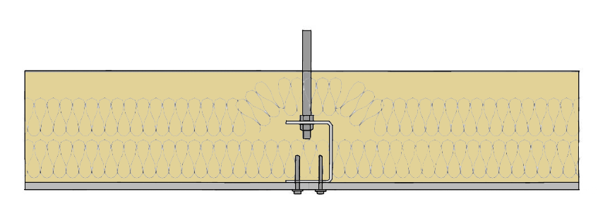
Perimeter channels of ceiling membrane fastened to surrounding construction with M10 or M12 all steel expanding anchors (or equivalent for alternative types of supporting construction) at 500mm maximum centres.
Primary channels at 1200mm maximum centres, supported from building structure above the ceiling membrane with steel drop rods at 1.5m centres. Threaded rods pass through clearance holes in the upper flange of the channels and are fastened with steel hexagon full nuts.
Diameter of drop rods such that the tensile stress within the rods does not exceed 6N/mm2 for fire ratings up to 240 minutes.
9.5mm Durasteel boards fastened to lower flange of steel channels with M5.5 steel self-drill and tap Tek screws at 200mm nominal centres. Fixings a minimum of 12mm from edge of sheet and a maximum of 50mm from corners. Length of fixing to be sufficient to ensure appropriate penetration of screw thread in accordance with screw manufacturer’s recommendations.
Longitudinal board joints coincide with primary channels, transverse board joints backed by steel channel the same size as the primary channels. Longitudinal and transverse channel members are either welded together or joined with steel angle cleats, minimum 60mm x 60mm x 3mm thick x 60mm long, fastened to each channel member with two M10 steel bolts and nuts.
Rock wool insulation, total of 120mm x 140 kg/m3 nominal density fitted with 2 x 60mm thick layers, one layer fitted over the Durasteel soffit layer by filling the channels and the second layer fitted over channels. Joints in layers of rock wool overlap by at least 150mm.
A layer of 1.5mm thick steel sheet is laid on top of the upper layer of rock wool. Where an expansion allowance is provided within the primary channels, steel jointing channels, minimum 50mm flanges x 3mm thick, are fastened to the primary channels with M10 steel bolts and nuts. The width of the jointing channel (web dimensions) should be such that it is a close fit within the primary channels.
On one side of the expansion gap the primary and jointing channels are connected with minimum two M10 bolts. On the opposite side the channels are connected, through slotted holes, with minimum two M10 bolts fitted with fusible washers. For fire attack from below, an expansion allowance of at least 6mm per metre is required for primary channels longer than 4m.
For fire attack from above, an expansion allowance of at least 6mm per metre is required for all sizes of ceiling.
As drop rods support the ceiling, the length and width of ceiling membrane is unrestricted.


Share/Like this page